
I. INTRODUCTION
The objective of this study was to determine the threshold linear
energy transfers (LETths) and cross-sections for single event
upset (SEU) and single event latchup (SEL) due to heavy ions.
LETth is defined as the maximum LET at which no errors are seen
at a fluence of 1.00E07 particles/cm2. SEU LETthis defined as
the minimum LET value to cause an effect at a fluence of 1E7
particles/cm2. SEL LETth is defined as the maximum LET value at
which no latchup occurs at a fluence of 1E7 particles/cm2. The
saturation cross section of the device is the point at which the
cross section curve becomes asymptotic.
II. TEST SAMPLES
Relevant characteristics of the devices are summarized in the
following table:
Device Type Mfg. Date Code Ser. No Technology
EEPROMs
HN58C1001 Hitachi ??? ??? CMOS/epi
SA28C256ERPDB SEI 9436 ???,??? CMOS/epi
SA28C256ARP SEI 9224 ??? CMOS
The SA28C256ERPDB (28C256) is a Space Electronics Inc. (SEI) device
with die bought from SEEQ (SEEQ Rev E). The die was actually
manufactured by Signetics and is a Signetics' Rev J version.
The SA28C256ARP (28C256A) is a Space Electronics Inc. (SEI) device
with die bought from SEEQ (SEEQ Rev E). The die was actually
manufactured by HMC and is known as process P512.
Sample devices were delidded in order to accommodate beam
penetration limits of the test facility.
III. TEST TECHNIQUES AND SETUP
A. Facility Usage
The test facility used was the Brookhaven National Laboratories
(BNL) Single Event Upset Test Facility (SEUTF)between January
24-25,1995. This setup utilizes a dual Tandem Van De Graaff
accelerator suitable for providing ions and energies for SEU
testing. The test devices are mounted on a device-under-test
(DUT) board inside a vacuum chamber.
The SEUTF uses a computer-driven monitor and control program to
provide a user-friendly interface for running the experiments.
Hard copies of the test data and graphs are also made available.
B. Test Hardware, Software and Control
Test hardware, software, etc,... consisted of a DUT board placed
in the test chamber, six feet of twisted pair ribbon cable, and
two PC-based testers, the Omnilab and VXI systems. Both testers
provide test patterns to the test boards and are capable of
capturing output when errors occur. The VXI enhances the error
capture by using an intrinsic compare and a custom-built FIFO
buffer board thereby reducing processing time and eliminating
the need for additional hardware on the DUT boards. Both
systems are capable of controlling the entire test setup,
digital counters, power supplies, waveform generators as well
as the BNL computer via an IEEE 488 bus.
C. Device Test Procedure
The test procedure was similar for all devices tested. All
tests were either dynamic in nature, (with the exception of
strictly latchup testing) meaning that the devices were
operating during the test at a nominal rate as they might in
a spacecraft application, or in a static mode were the devices
were merely biased during irradiation. In dynamic testing,
power was first supplied to the device. A stimulus pattern was
then loaded and the device began to function normally while
exposed to the ion beam. Outputs from the device were
constantly monitored by either the Omnilab or VXI and all
errors accumulated until either fluence was reached or a
latchup condition occurred. In the case of the latter, power
and beam to the device were terminated and the test run ended
prematurely. Otherwise, error counts were logged to the hard
drive. Static mode testing varied by pre-loading the DUT with
a known pattern, irradiating the device, then reading back from
the device looking for errors. Two to three samples are
typically used for testing to gain statistical validity. All
DUTs were tested under a (nominal) 25 degrees celsius.
EEPROM Modes tested:
Static - device loaded prior to beam, irradiated to a
known fluence, then read back for errors
Read only - device loaded prior to beam and read
continuously during irradiation.
Write in byte mode - device programmed byte-by-byte during
irradiation, then verified post-irradiation
Write in page mode - device programmed page-by-page during
irradiation, then verified post-irradiation
Test pattern used: checkerboard.
Both bits in error and bytes in error were monitored. (If the
2 numbers are the same, all SEUs are single bit data errors.
If numbers are not equal, control errors may have occurred as
well during write operations.). Unfortunately, the bit counter
test hardware failed in the middle of testing. Only byte errors
are discussed below.
D. Ion Beam Usage
The following table summarizes the ions typically used for
testing.
ION ENERGY (MeV) LET (MeV*cm2/mg) at 0 deg.
F-19 136 3.45
Cl-35 195 11.8
Ni-58 262 26.6
I-127 305 59.6
Additional effective LET values were attained by varying the angle
of incidence of the ion beam to the device. All LETs discussed
are in MeV*cm2/mg.
IV. RESULTS AND DISCUSSIONS
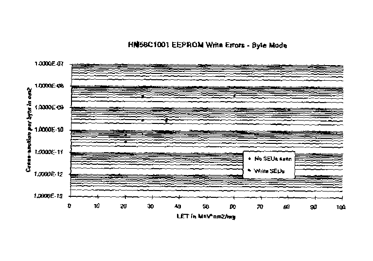
HN58C1001
This device, from Hitachi, is a 1 Mbit (128Kx8) EEPROM, Nominal
Vcc/Icc for this device (standby/operating mode) is 5V/5-9 mA .
SEL current was set to 50 mA.
No SEUs were seen in static or read mode of operation up to
maximum tested LET of 80.
Test results for the write byte and write page modes were
equivalent. Figure 1 illustrates the test results for the write
page mode. LETth was 18.
SEL-only testing was performed on this DUT in Nov. 1994. No sign
of latchup was observed up to the maximum tested LET value of 90.
28C256A
This device, from SEI, is a 256 kbit (32Kx8) EEPROM, Nominal Vcc
for this device (standby mode) is 5V/16-25 mA . SEL current was
set to 80 mA.
No SEUs were seen in any mode of operation up to maximum tested
LET of 14.9. However, SEL occured at next LET tested. SEL LETth is
between 14.9 and 26.2. Both test samples failed with an Icc for
these devices exceeding 1.5A after SEL occurence.
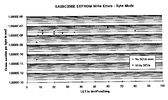
28C256
This device, from SEI, is a 256 kbit (32Kx8) EEPROM, Nominal Vcc
for this device (standby mode) is 5V/6-22 mA . SEL current was set
to 80 mA.
No SEUs were seen in static mode of operation up to maximum
tested LET of 80. Sporadic SEUs (no statistical data) were seen on
read mode operations starting at an LET of 11 with a maximum
device byte cross-section of < 1E-6 cm2.
Test results for the write byte and write page modes were
equivalent. Figure 2 illustrates the test results for the write
page mode. LET th was 7.
SEL-only testing was performed on this DUT in Nov. 1994. No sign
of latchup was observed up to the maximum tested LET value of 90.
V. SUMMARY
The findings of these tests are interpreted in the following.
We typically divide SEE test results into the following four
categories.
Category 1 - Recommended for usage in all spaceflight applications.
Category 2 - Recommended for usage in spaceflight applications, but
may require some SEE mitigation techniques.
Category 3 - Recommended for usage in some spaceflight applications,
but requires extensive SEE mitigation techniques or SEL recovery
mode..
Category 4 - Not recommended for usage in any spaceflight
applications.
Category 2 devices for this test trip are:
SEE only: HN58C1001, 28C256
Category 4 devices for this test trip (SEL only) are:
28C256A (Low SEL threshold and high Icc for SEL)
VI. ACKNOWLEDGEMENTS
Special thanks to the test team and on-site support of Jim
Kinnison of APL.
Home
Last Revised: February 03, 2010
Digital Engineering Institute
Web Grunt: Richard Katz